

Military Cable Harness Guide: Design, Build and Test
A military cable harness bundles wires, coaxial cables and connectors into one tested assembly. How defence harnesses are designed, built and electrically tested.
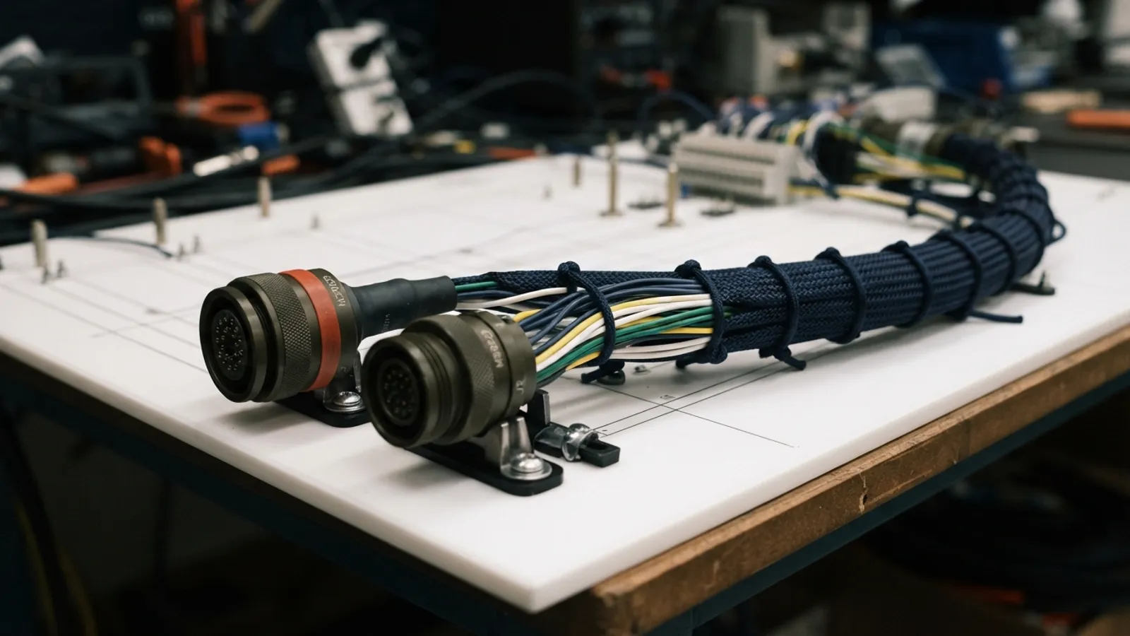
A cable harness — also called a wire harness or cable assembly — is an organised bundle of wires, cables and connectors that carries power, signals and RF between the units of a system. On a military platform such as a UAV, an armoured vehicle or an aircraft, the harness is the nervous system: if one contact is wrong or one insulation is damaged, a navigation sensor, data link or actuator stops working. This guide explains what makes a military cable harness different, how it is built and how it is tested.
What is a cable harness?
Instead of routing every wire separately, a harness groups them into one assembly built to a drawing. Wires are cut to length, stripped, terminated with crimped contacts or solder joints, inserted into connectors, bundled, labelled and protected with sleeving or heat-shrink. The result is installed as a single part, which shortens assembly on the platform and removes wiring errors.
- Power lines feeding units and actuators
- Signal and data lines such as serial, CAN or RS-422 buses
- Coaxial lines carrying RF between antennas, receivers and radios
- Grounding and shielding paths that control EMC
What makes a military harness different?
Defence platforms expose wiring to vibration, shock, temperature extremes, moisture, fuel and abrasion, often for decades. A military cable harness is therefore built for reliability, traceability and repeatability rather than lowest cost:
- Rugged circular or Micro-D connectors chosen for the environment
- Wire and insulation rated for the temperature, fluids and abrasion they will see
- Controlled crimping and soldering processes that repeat unit after unit
- Shielding and grounding designed for electromagnetic compatibility
- Labelling and documentation so every conductor can be traced
- Electrical test of every harness, not just samples
How a harness is built, step by step
- Cutting and stripping — coaxial and multi-core cables are cut to length and their insulation is removed in a controlled, repeatable way.
- Termination — contacts and terminals are crimped onto the conductors with a press, or joints are soldered on temperature-controlled stations.
- Connector assembly and lay-up — contacts go into the connectors and the wires are routed and bundled on a board that follows the drawing.
- Protection and marking — sleeving, heat-shrink and labels are added.
- Inspection and test — joints are inspected under magnification and the finished harness is tested automatically.
Electrical testing: continuity and insulation
A harness can look perfect and still be wrong. Automatic harness testers check every connection point against the wiring list. Continuity testing confirms that each conductor goes where the drawing says and nowhere else — no opens, no shorts, no mis-wires. Insulation testing applies a voltage between conductors to confirm the insulation is intact. Because the test program comes from the same wiring data as the drawing, the result is objective and repeatable for every unit.
RF cable assemblies are also measured with a vector network analyser: return loss and transmission characteristics show whether a cable and its connectors will carry the signal without reflections — important for the antennas and data links described in our RF PCB design guide.
Design tips that make harnesses easier to build
- Freeze the wiring list early and keep it under revision control
- Separate power, digital and RF runs to limit coupling
- Choose connectors and back-shells for the platform’s environment
- Leave service loops where units must be removed for maintenance
- Agree on test criteria — continuity, insulation and, for RF, return loss — before production starts
Cable harness manufacturing at Sağlamtek
Sağlamtek builds cable harnesses in Ankara. Cables are cut and stripped on Schleuniger machines, terminals are crimped on a Mecal electromechanical press, joints are soldered on Weller WXsmart stations and inspected under a digital microscope, and harnesses are verified on two MK Test Systems Automeg D1500 automatic test units. RF cables and connectors can be measured on a Rohde & Schwarz ZNLE18 vector network analyser up to 18 GHz.
To quote a harness we need technical drawings, wiring diagrams or a sample harness. See the full equipment list on our cable harness manufacturing and electrical test page, or request a quote.

Written by
Sağlamtek Engineering Team
RF, antenna & navigation engineering · Ankara
Articles on this blog are written by the engineers who design, test and build Sağlamtek’s anti-jam GNSS, RF, antenna and radar products at our R&D Center and manufacturing facility in Ankara.