
BLDC Motor Driver Guide: How FOC Motor Control Works
What a BLDC motor driver does, how field-oriented control (FOC) works, which feedback to choose and what matters in stabilised defence mechanisms.
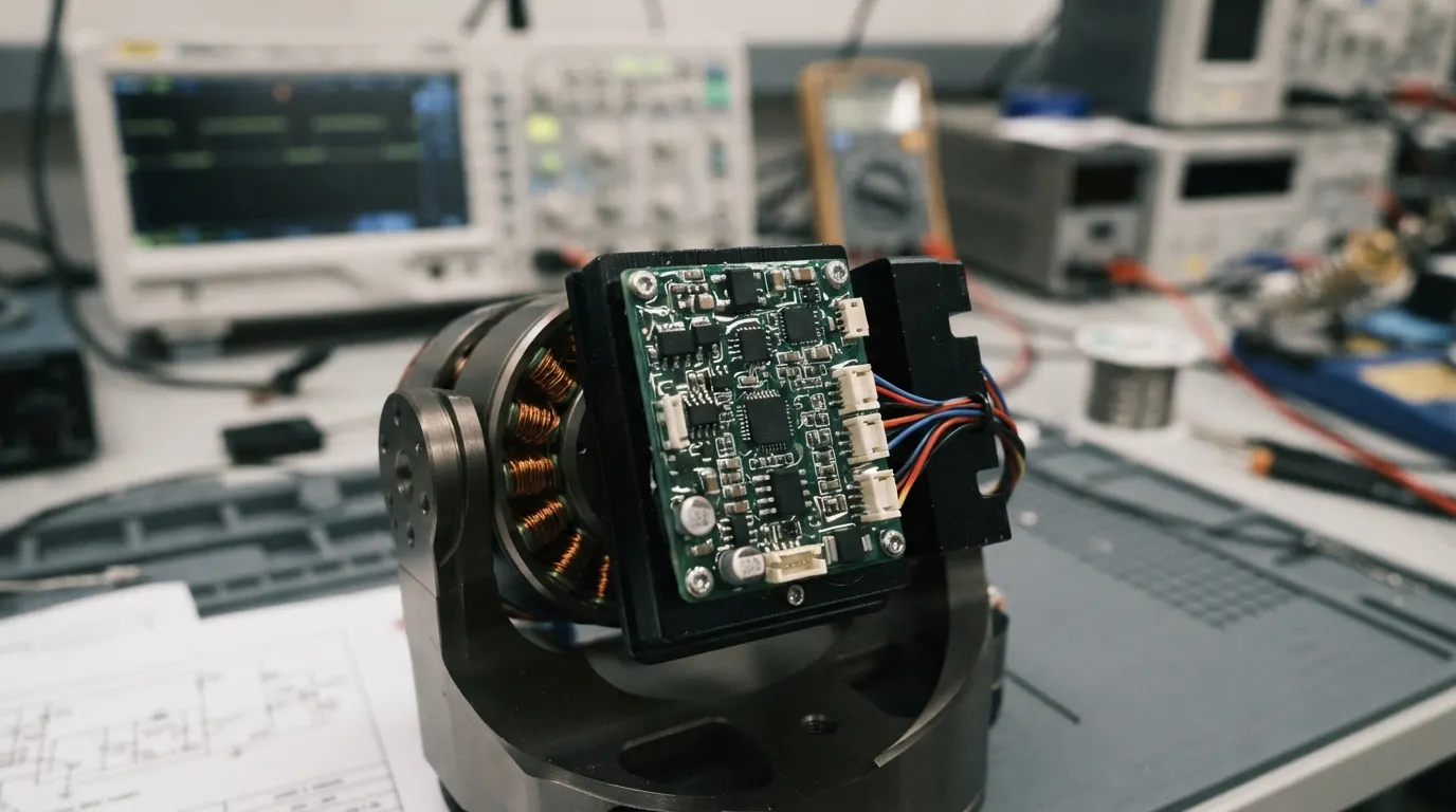
A motor driver is the power electronics between a controller and a motor: it takes position, speed or torque commands and turns them into precisely switched currents in the motor windings. For brushless DC (BLDC) motors the driver also replaces the mechanical commutator of a brushed motor — it decides, thousands of times per second, which phase gets current and how much. In gimbals, turrets and antenna positioners, the quality of that decision is what you see as smooth, quiet and accurate motion.
Why BLDC motors need a dedicated driver
A BLDC motor has permanent magnets on the rotor and three phase windings on the stator. To produce torque, the stator field must stay ahead of the rotor magnets as the rotor turns. The driver therefore needs to know the rotor angle, switch a three-phase inverter at the right moments and limit current so the motor and electronics stay inside their ratings. Without that electronics the motor simply does not turn.
Trapezoidal (six-step) control vs FOC
The simplest BLDC drivers use six-step, or trapezoidal, commutation: two phases conduct at a time and the pattern changes every 60 electrical degrees, usually based on Hall sensors. It is easy to implement but produces torque ripple, which shows up as vibration and audible noise at low speed.
Field-oriented control (FOC) measures the phase currents and transforms them into two components in the rotor’s reference frame: Id, which acts along the magnet axis, and Iq, which produces torque. The controller holds Id near zero and regulates Iq directly, so torque is smooth across the whole revolution and the motor can be controlled precisely even near standstill.
- Smooth torque with very low ripple — important for stabilised optics and pointing
- Accurate low-speed and holding performance
- Higher efficiency because current is used only where it produces torque
- Better dynamic response in cascaded position and speed loops
Control loops: torque, speed and position
Most servo drivers run cascaded loops. The innermost current (torque) loop is the fastest, typically a PI controller acting on Iq. A speed loop sits around it, and an outer position loop — often PID — sends speed or current set-points down the chain. Being able to select torque, speed or position mode lets the same driver serve a stabilisation axis, a scanning antenna or a positioning stage.
Choosing motor feedback: encoder, Hall or sensorless
- Incremental encoder (A/B/Z): the highest resolution, needed for precise positioning and low-speed stabilisation
- Hall sensors: coarse rotor position, robust and simple, suited to speed control and start-up
- Sensorless back-EMF: no sensor wiring, useful where space or reliability rules out sensors, but needs speed to estimate rotor angle
In military mechanisms a driver that supports several feedback types — and reacts safely if one fails — gives the integrator more freedom. A safe stop on encoder loss, for example, prevents an uncontrolled movement of a weapon station or sensor head.
What matters in a defence motor driver
- PWM frequency: switching above the audible band (around 16 kHz and higher) keeps the acoustic signature low
- Protection: over-current, stall, over/under-voltage and thermal shutdown
- Interfaces: CAN and RS-422 are common because they are robust over long, noisy cable runs
- Telemetry: position, speed, current, bus voltage and temperature for health monitoring
- Environment: wide temperature range and conformal coating against humidity and contamination
Sağlamtek’s FOC motor driver
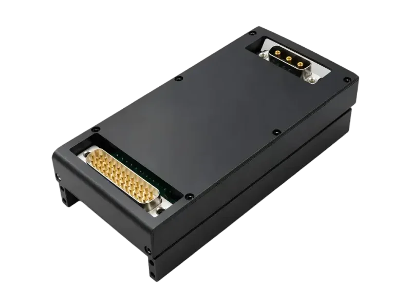
The SGT-FDMSCK-YKD-AA is a FOC motor driver for BLDC and DC servo motors, designed and manufactured by Sağlamtek in Ankara. It offers torque, speed and position modes with a cascaded position PID and current PI loop; works with A/B/Z encoder, Hall or sensorless back-EMF feedback; delivers 12 A continuous and 24 A peak; switches at 16–24 kHz for a low acoustic signature; and communicates over RS-422 and CAN. It is conformal coated for −40 … +85 °C and protects against over-current, stall, voltage faults and over-temperature, with a safe stop on encoder loss.
Typical uses include EO targeting and stabilisation, radar and antenna positioning, remote weapon stations on armoured vehicles, and UAV, UGV and robotic mechanisms. If your motor, load or interface needs differ, our engineers can review the mechanism and adapt the driver.

Written by
Sağlamtek Engineering Team
RF, antenna & navigation engineering · Ankara
Articles on this blog are written by the engineers who design, test and build Sağlamtek’s anti-jam GNSS, RF, antenna and radar products at our R&D Center and manufacturing facility in Ankara.